Rotary drilling rig is a kind of construction machinery suitable for hole-forming operation in a variety of pile foundation engineering. The power device is the main working mechanism of the rotary drilling rig, and its performance directly affects the performance of the rotary drilling rig. The power device is the power source of the rotary drilling rig, which drives the drill pipe and the drill bit to rotate, and can provide the pressure and lifting force required for drilling. When the power device drives the drill pipe and the drill bit to rotate, the rotating speed and torque can be automatically adjusted according to different soil geological conditions to meet the changing working conditions. Generally, the power unit adopts low speed and high torque operation mode for normal drilling operation.
Structural Analysis of 1. Power Plant
The power device is composed of variable hydraulic motor, reducer, shock absorber, reduction box, pressure plate, sliding frame, etc. (see Figure 1).
(1) Shock absorber When the drilling depth exceeds the length of the first layer of drill pipe, the fixed flange on the upper part of the drilling rig column is placed on the welding of the power head pressure plate, and the power head will be impacted when drilling or lifting, especially In unexpected situations such as sticking, the impact on the power device is greater. At this time, the shock absorber can relieve the impact on the power device and protect the power device from damage.
(2) The pressure ship is connected with the shaft sleeve. When the rotating bucket is filled with muck to lift up, it collides with the collision body on the rotating bucket and opens the rotating bucket to discharge the muck.
(3) The guide part of the power head number of the sliding frame is fixed with the power box through the coupling plate and pin shaft, and the power head is guided along the column guide rail during the working conditions of pressurized drilling and pulling up the power head.
(4) the reduction mechanism through the size of the external gear meshing, for the whole machine to achieve low speed high torque drilling transmission power.
2. working principle
The power device of the rotary drilling rig usually drives the planetary reducer by one to three hydraulically controlled variable motors to drive the large and small gears to mesh, thereby transmitting torque to the telescopic drill pipe. Usually, one to three small gears are used to drive the hollow large ring gear at the same time. Make the overall layout of the whole machine compact and the force more reasonable. The large gear ring of the existing rotary drilling rig power device reduction box is connected by a slewing bearing.
Structural form and three-dimensional model of 3. power plant
The driving torque of the power unit reducer currently used can reach 120-760kN · m for drilling rigs produced in Europe, while only 50-400kN · m for drilling rigs produced in China. The reducer that transmits such torque must adopt gears with large modulus, wide tooth surface and high alloy material; the gear box generally adopts welded structure. In general, large torque is not necessary for itself. This is mainly used in deep soil layer with large penetration, soft rock layer, broken rock layer with strong joint nature or when providing power for casing spinning. Fig. 2 shows several common power plant structures of vehicles at present, all of which are driven by hydraulic pressure.
The size of the 4. three structures gear materials are 42CrMo, the specific performance parameters are shown in Table 1. The gears are in external meshing mode. The large ring gear is set as a fixed constraint, the pinion is a fixed hinge constraint, and the gravity load is applied. The single-motor structure pinion is loaded with 100kN · m torque, and each pinion of the motor structure is loaded with 25kN · m torque, and each pinion of the three-motor structure is loaded with 135kN · m torque.

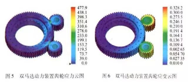
After the above analysis, it is found that the three kinds of reducers are within the allowable range of stress size and distribution or deformation, and the salt reducer can better meet the requirements of rotary drilling rig drilling. The maximum stress sound of the three deceleration mechanisms occurs at the pinion, and the maximum stress is 447.4Mpa, 447.9Mpa and 487.6Mpa respectively. The safety factor is 2, which is less than the yield strength 930Mpa of the material. According to the strain nephogram, the deformation of the pinion is the largest, the maximum strain is 0.25mm, 0.32mm and 0.74mm respectively, and the maximum deformation is much smaller than the geometric size of the gear. It can be seen that these kinds of reducers can meet the needs of torque transmission.
5. Conclusion
In this paper, through the SolidWords software modeling, combined with the Simulatiom finite element analysis software to complete the static simulation analysis of several reducer structure, theoretically analyze the reducer in the normal drilling operation conditions of stress and strain. Through the above analysis, it can be seen that the maximum torque of the single-motor deceleration scheme can be transmitted 100kN · m, the maximum torque of the dual-motor deceleration scheme can be transmitted 250kN · m, and the maximum torque of the three-motor deceleration scheme can be transmitted 405kN · m. Compared with the single motor power device scheme, the reducer driven by two motors or three motors at the same time can transmit more torque, which enhances the reliability of the power device reducer.